


Last Uploaded: January, 2010
The Shimizu Institute of Technology, an urban research center


Personal air conditioning
 |
|||
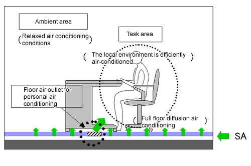
| Conceptual diagram of personal air conditioning | |||
 |
 |
 |
|
The main building adopts floor-supply displacement air-conditioning system as well as floor air outlets for personal air conditioning (hereinafter referred to as "personal air outlets") developed to fulfill the personal requirements of workers for the thermal environment. For the ambient area, uniform air conditioning is ensured by air-permeable tile carpets. Personal air outlets also contribute to efficient local air conditioning of the task area. At the same time, the air conditioning in ambient areas is relaxed to save energy.
Air conditioning, ventilation, and lighting control using PHS functionality to measure the number of people in the room
 |
|||
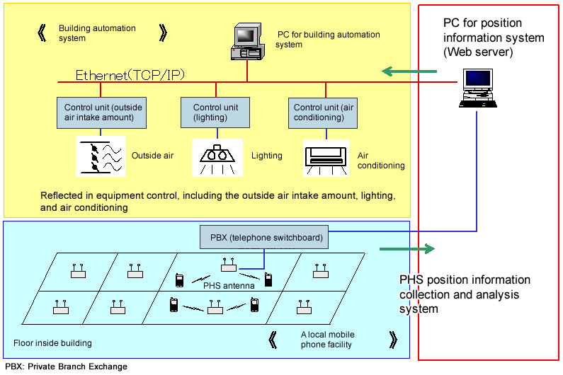
| Energy-saving system using PHS functionality to measure the number of personnel in the room | |||
 |
 |
||
1) Outside air intake amount optimization control
The amount of outside air intake to be introduced into each zone is adjusted to the proper amount based on the number of personnel in the room to reduce the outside air load.
2) Lights-out and air conditioning stop control during overtime work
The lighting and the air conditioning system for the zone will be turned off during overtime work as soon as the number of people in the zone becomes zero.
Biotope
 |
|||
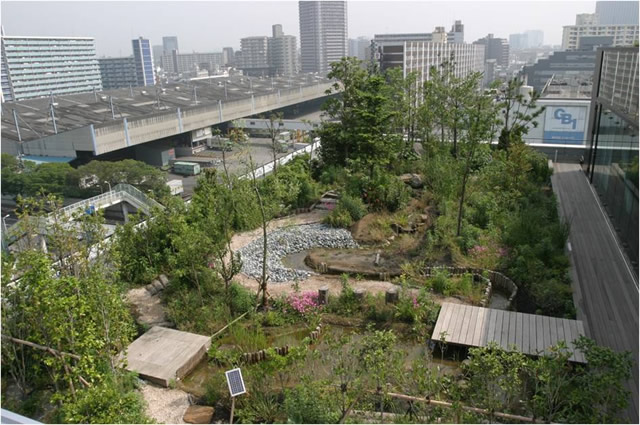
| Full view of roof biotope | |||
 |
 |
 |
 |
The main purpose of the ground biotope is to restore the relationship between people and wildlife in an urban area. Additionally, it was constructed to create green space with high added value and thereby establish a harmonious relationship with the community and fulfill the social responsibility of a company.
This biotope was constructed with three "Saisei (which means both restoration and recycling in Japanese)" goals to achieve: 1) the restoration of the natural ecosystem in the urban area, 2) the recycling and circulation of resources, and 3) the restoration of the living environment.
Previous Building |
 Next Building Next Building |
These cases are described based on assessment results obtained using CASBEE.
CASBEE is a method for rating the environmental performance of buildings using Building Environmental Efficiency (BEE) as an indicator, which is based on the results of separate scores obtained for Q-1~Q-3 (Quality) and LR-1~LR-3 (Load Reduction).
CASBEE is a method for rating the environmental performance of buildings using Building Environmental Efficiency (BEE) as an indicator, which is based on the results of separate scores obtained for Q-1~Q-3 (Quality) and LR-1~LR-3 (Load Reduction).
E-mail:  | Copyright © 2008 Institute for Building Environment and Energy Conservation, All Rights Reserved.
| Copyright © 2008 Institute for Building Environment and Energy Conservation, All Rights Reserved.